Admittedly, I have not been the best blogger this year. In my defense, I have been busy making videos and building robot cars. So I was happy to see this article about Overpressure Protection Systems (OPS aka HIPS aka HIPPS) from the good folks over at Emerson Automation Solutions. It is always easier to riff on someone else than to start from scratch.
The article is a nice little overview of OPS design with an emphasis on the benefits of newer technologies, such as smart transmitters, partial stroke testing positioners, asset management systems, etc. And not coincidentally, Emerson is happy to sell you many of these items!
 Chemical Engineering
 I don't have any criticisms of the article per se, but I found myself thinking "Yeah, but..." a few times while reading it. Having designed and commissioned systems like this in the past, I am going to provide some observations and tips that were not covered in the article.
Typical Overpressure Protection System
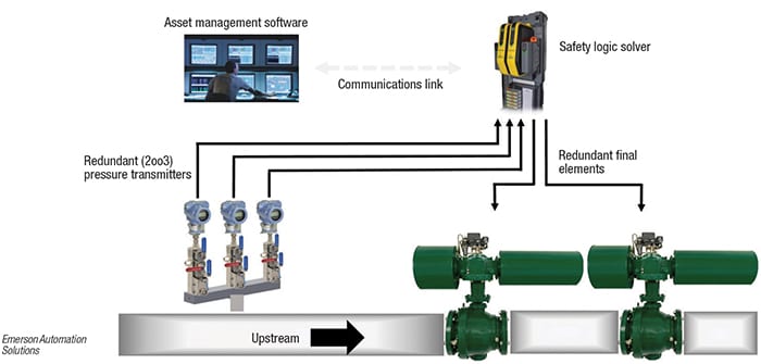
For reference, the article provided the following image as an example of a typical Overpressure Protection System:

Figure 4. This typical OPS monitors the feed to a reactor or other part of a process unit for high pressure
My comments will concentrate on the two shutdown valves, and specifically on the pneumatic actuation systems.
Surprising Regulator Behavior
As I'm sure you remember from my earlier blog post Fail Safe Regulators, it is critical to understand and consider how your regulators will behave on loss of incoming instrument air. Modern regulators may bottle-up the air supply in the valve when the designer intended the valve to fail closed on loss of air.
This non-failsafe behavior may be adequate for many SIS applications since the logic of the safety function will still drive the valve to the safe position if needed. However, this needs to be analyzed carefully to ensure there are no unexpected behaviors, especially in transient conditions.
For example, consider the case where instrument air is temporarily lost and then returns. For the valves in the simple OPS system above, this may be OK. But remember that the sizing basis for relief sizing generally depends on certain valves failing closed and others failing open and may make assumptions about "double contingencies".
If the overpressure protection designer made incorrect assumptions about valve behaviors on loss of instrument air, the relief design could have significant errors. This becomes especially risky when there a mix of older and newer regulators in the same unit.
Solenoid Minimum Differential
As safety-certified positioners become more common and partial stroke testing more widely accepted, it has become increasing common to see SIS valves that mix solenoids and positioners on the same valve. The example in the figure above has a positioner and solenoid in a 1oo2 voting configuration on each valve.
In a mixed 1oo2 configuration like this, you want to have the solenoid closer to the actuator, as shown in the figure. This is so that a failure of the positioner cannot "override" the solenoid and bottle up the actuator air, defeating the 1oo2 voting.
Here is where the problem comes in. With larger valves, larger actuators, faster response times, and/or long cable runs, it is often preferred to use a pilot operator solenoid. However, many pilot operated solenoids have a specification for minimum differential pressure across the Inlet-Outlet of the solenoid. For example, if the input pressure drops close to the outlet pressure, the solenoid will behave unpredictably.
Unfortunately, when the positioner trips or does a partial stroke test, this is exactly what happens. For the positioner to start exhausting any air from the actuator, the dP across the solenoid must be negative!
The result of this type of problem is usually slow and/or unpredictable stroke times for the valve. The fix is to use a solenoid with no minimum dP requirement. This is a common feature of direct acting solenoids.
Spurious Trip Rate
With the shutdown valves voted 1oo2 and the pneumatics on each valve voted 1oo2, the overall voting for a spurious trip of the final elements is 1oo4. This jumped out at me as an odd design choice since the sensors are 2oo3 voted and presumably connected to a snazzy high availability logic solver.
My back of the envelope calculation suggests that the spurious trip rate for the valves will be at least 100x worse than the rest of the system. In practice, these numbers may be even worse since FMEDA analysis often underestimates the real-world conditions that lead to things like solenoid coil burnouts.
There are potential solutions. For example, with the 1oo2 valves and regular partial stroke testing, it may be possible to rearrange the pneumatics such that the positioner and solenoid are 2oo2 voted instead of 1oo2. This arrangement could likely still meet SIL 3, although I am not running calculations.
Overpressure Protection Wrap Up
Obviously, Overpressure protection systems (OPS), HIPPS, and high-SIL systems are a very complex subject, and I haven't really delved into that here. The decision to use instrument-based relief mitigation vs. traditional relief valves involves many tradeoffs.
This post just highlighted a few of the "gotchas" you may run into when engineering a high reliability valve system for OPS / HIPPS. The items covered above are very specific, but I will leave you with these general guidelines:
- Don't leave the engineering of complex actuation systems up to the valve integrator
- Use direct acting solenoids where you can, and be aware of minimum dP requirements for piloted SOVs
- Always review pneumatic hookups and component data sheets prior to valve assembly
- Have valve integrators do a fully assembled stroke test before FAT
- Always, always do a comprehensive factory acceptance test for SIS valves
Thanks for reading! Please like and follow us on LinkedIn! You can also support us (and help yourself!) by shopping for books.